RPI Printer
Kaichen Wei(kw573) Neo Yuan(zy393)
December 12 2019
Introduction
Unlike traditional ink-jet printer or laser printer that needs a ink box, an RPI printer can use a pencil or a pen to print the input characters and image in a grey scale. Also unlike the tradition printer that has to work with a computer, the RPI printer is a integrated printer that allow the user to directly input to and instantly get the image. The future of the RPI printer will be printing anywhere, anytime.
Objective
1. RPI printer is to accept typed text and graphic images from a computer and transfer it to paper
2. RPI printer will automatically transfer the colorful image to gray scale and print
3. By switch the drawing tools the RPI printer will be able to draw differnt styles
Design
The design of the RPI printer is to utilize the protable feature of the Raspberry pi to create a integrated printer that can do inputing and printing at the same time. The group used a wooden chasis similar to a traditional printer instead of a angular printer to provide a precise and stable structure. In addition, the software design of the RPI printer is also based on the idea of the gray scale and will thus has a great performance on printing the whole image compare to other angular printer.
Hardware Design
The first trial the group made for this project is to try on a pre-designed allen 920E-XY Datagraph Plotter as shown in the figure 1. This plotter is a device made by the allen company to allow the machine to control in the x axis and y axis to draw precise drawing. The group start the project on this device. The group first connect the plotter directly to the power supply and use the control panel to move the plotter vertically and horizontally. However, when the group transfer from the physical button to a connection to a RPI, the group burned the GPIO pins that inside the RPI. The reason for that failure is because of the difference between the voltage requirement. RPI provide a 3.3V power supply while the device may need more, and the group at first thought they are the same and thus burned the RPI. Afterward, the group decided to change to plan B, which is build the physical structure by hands.
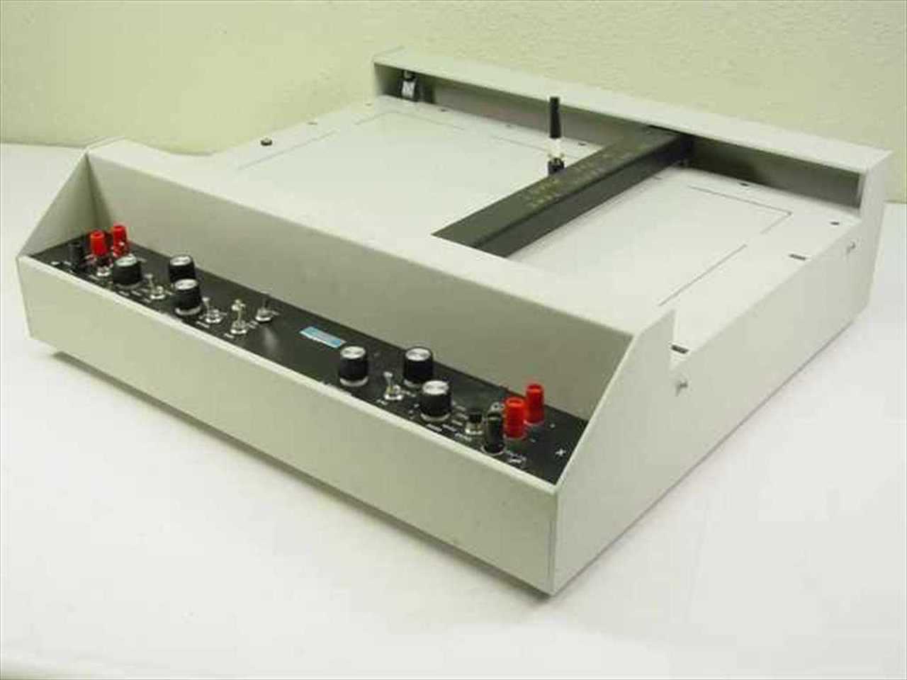
Figure 1. Allen 920E-XY Datagraph Plotter
As mentioned above and showed in the figure below, the hardware structure of the RPI Printer is a wooden chasis. The group chose wood as the material for the chasis is because of the convenience to obtain the wood and the cost of the wood is relatively low which will help to save the budget of the group. In addition to the wood, the group used four steel rods to create a sliding shaft for the printer to move.
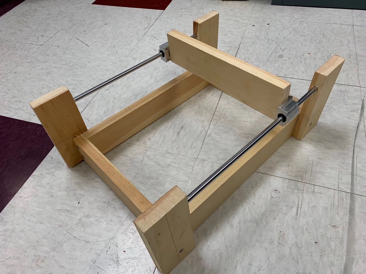
Figure 2. First Prototype of The Printer
This first design does not work well because the middle wood restrict the printer to move horizontally. Besides, the middle plank also provide no space for the group to install a step motor for the z axis. So the group modify the plan and use two wooden blocks in the x axis side to attach the rods for moving, and use two rods between two x axis for fixation. Between the two rods in the middle, the group attach a wooden block to attach the steel fixator and for further fixing of belts. Afterward, the group drill in the middle wood to save a place for the pencil and start to attach the step motors.
The group spent nearly one week on this process because drill a hole with the right size to place the pencil is not a easy job. The group continously experienced the distance between the pencil and the gear is too large that the gear will not be able to run the pencil, and the distance between is too small that the gear cannot even move. After several adjustment and testing, the group decided to stick with the design and finally find out the best place for the pencil to stay. Otherwise, the group will need to have a plan B for the z axis. The alternative design of the x axis and y axis works well, and is showing below.
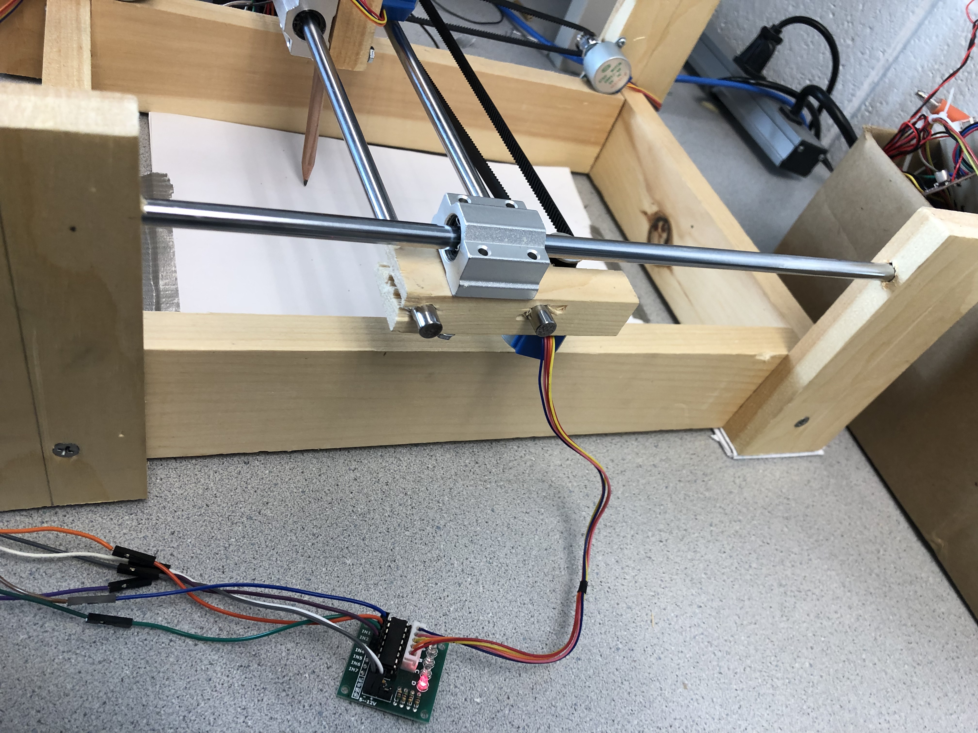
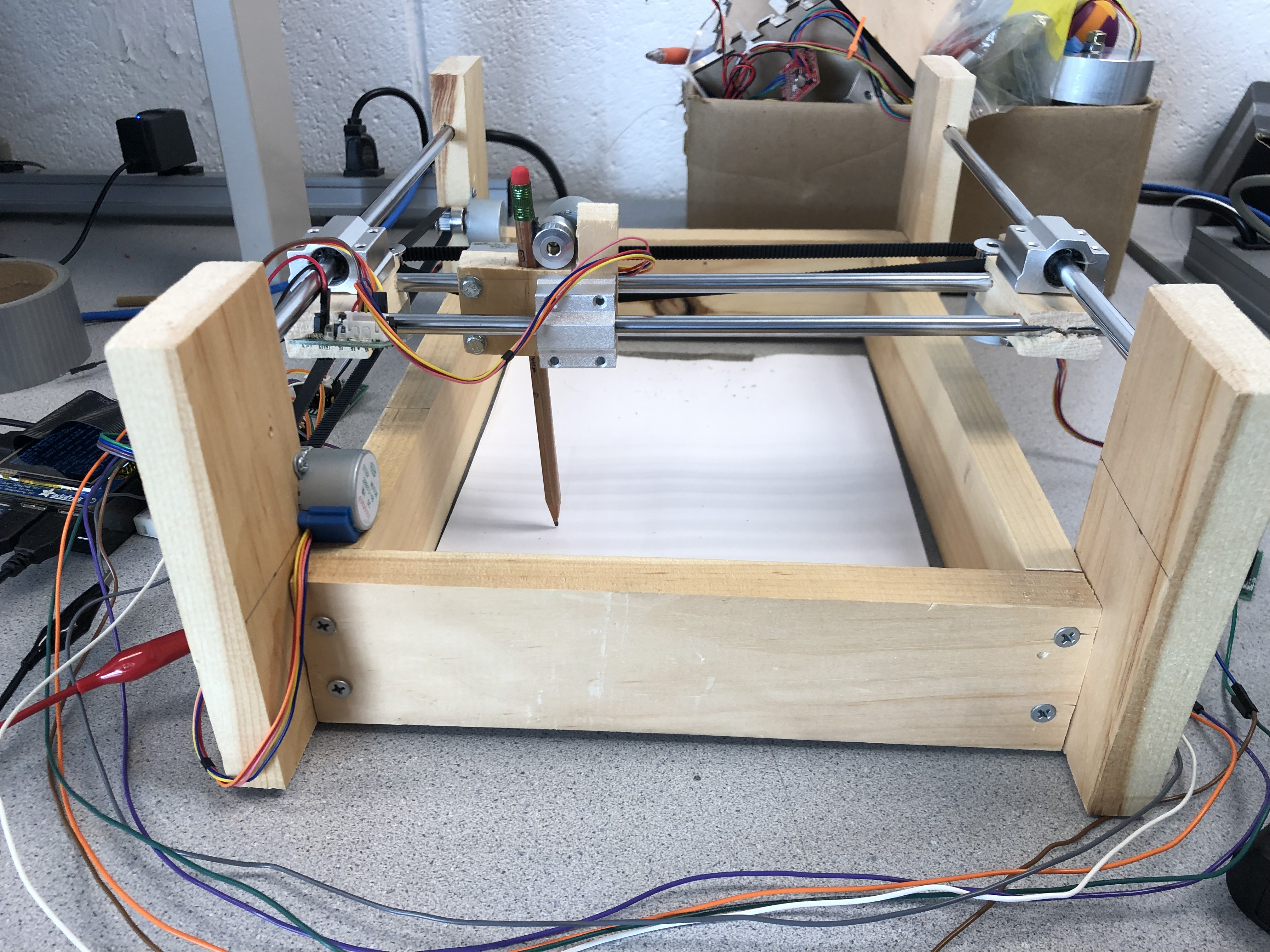 Figure 3. The alternative design of the chasis
After the design of the chasis succeed, the group started to install motors in the chasis to build the motion part of the printer. The motor the group used in this project is a step motor named 28BYJ-48 - 5V Stepper Motor. The reason the group chose step motor instead of normal servo is because of the precision the step motor can provide. The step motor will move base on the pulse, which allows the motor to rotate in eight directions. The image of the motor is listed in figure 4.
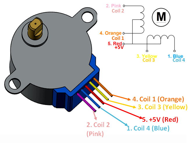 Figure 4. Image of Step Motor
Step motor will be connected to a driver with four wires to transmit the pulse, and for each wire, it will represent the pulse in one direction. Details of the driven will be explained in the software design part. In addition to the explaination of the motor itself, the design of the installation of the step motor utilized 12 GPIO pins in total. As shown in the figure 5 below, the group use each of 4 GPIOs for x axis and y axis to control motors in x direction and y direction. The reason for this design is first to save some GPIO pins for future development. In addition, control motors in the same direction by the same GPIO will benefit the motors to work synchronously. The group use another four GPIOs to control the pencil in the z direction.
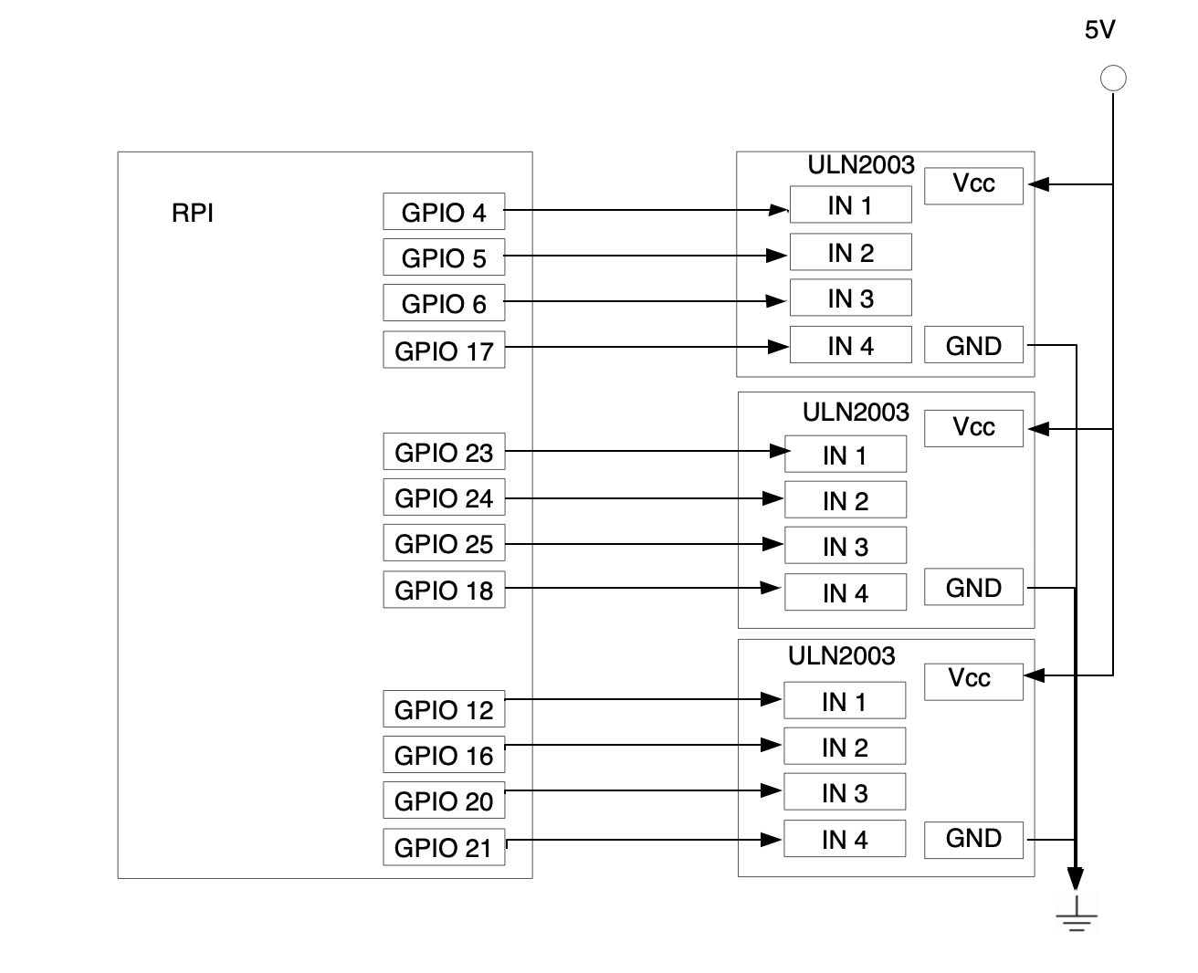 Figure 5. GPIO Connection
Finally, the group assemble all motors and get the picture below. And start to test each motor running function, the detail information for the testing will be included.
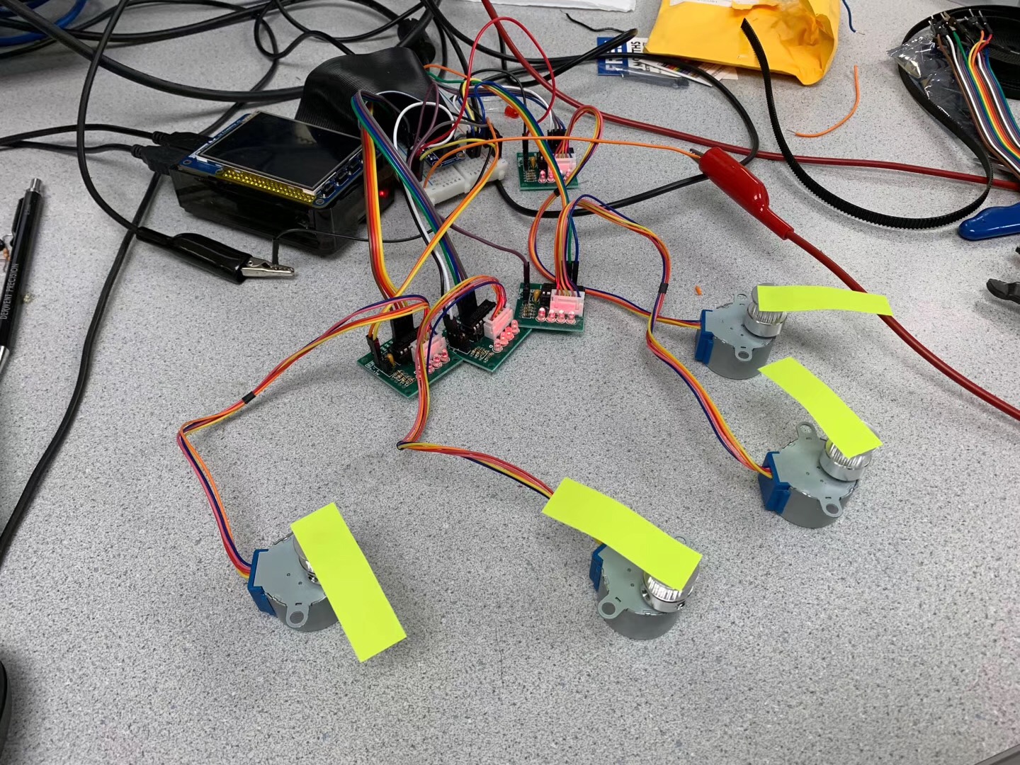 Figure 6. Wire Connection of the Step Motor
In general, the 3-D printing could be a great solution for this problem because the parts will be perfectly fits, however, the resources for 3-D printing is limited and will take a long time to wait. Time, is something the group missing at that time. The group indeed spent a great amount of time to cut the wood and drill the hole with appropiate size, while sometimes a small misdesign will require the group to redo every steps of assemblying. The final design of the hardware structure is workable, however, there exist possible methods for improvement. Software Design
The software design can be divided into two parts, which includes the software driving for the step motors and the design of the logic and the algorithm of the program.
The first part of this section the group will talk about the driving of the step motors. For the motivation of stepper motors, the principle of driving stepper motors is to give different pulses to the motor in order to make the motor rotate. There are in total four kinds of pulse input and 8 phases that it can change as shown in the figure. We need to give the pulses in sequence in order to rotate the motor. If the sequence of impulse is reversed, then the rotation direction will also be reversed. Four pulse input for every motor are connected to 4 GPIO pins to give the input to motor driver, and motor driver will be connected to motor for final controlling.
 Figure 7. Driving of the Step Motor
The other part of the software design is the design of the program the group use to print. The idea of designing software is to let the plotter become a printer and the pencil will go through the pixels row by row in order to draw the whole picture. First of all, a picture is used as the input to the program as the original picture. Secondly, the program will retrieve the RGB values for every pixel and convert them into greyscale. After getting grayscale picture, the group define a threshold for every pixel whether it is needed to be drawn. After all these preprocessing steps, the group then start to enable the motor to draw the pixels line by line.
In the software part, the orginal design is to draw the input image base on the gray scale pixel points value, and convert into the strength of the z axis. However, because of the limitation of the handcraft wooden structure, the z axis cannot be precise, which prevent the group to realize this function. In addition, the orginal x axis and y axis design did not work well because the belt was fixed to different objects. The belt in the previous y axis was fixed to a wood block, which provide a stable movement is fine, however, the orginal x axis is instable and always stuck because of the force is uneven. So the solution of the software design is to switch the x and y axis. Because y axis will only need to move once by each pixel, it will have the least influence if it stuck.
Testing
The first two weeks of the projects focused more on the hardware assemble while the least
week the group focus and spent more time on the software design and testing. The testing can be divided into two parts,
the first part is the testing for invidual motors and the second testing is the whole RPI printer to ensure the function
can work properly.
For the motor test, we firstly connect 12 GPIO pins in total for 3 motors(4 pins each). Since the stepper motor can be divided into 4 input for 8 phases, we write the code to make the motor move clockwise by giving the pulse in certain sequence. After successfully make them move in one direction, we reverse the order of the sequence in order to make the motor move counterclockwise. In this test, since we think that we may use multiple motors to control the printer together, we also create multiple thread to control the motors independently.
For the integrated testing, the group start to print the Cornell ECE Logo, figures about
this test will be presented below. In this test, the group realized that the orginal x axis is not stable and sometimes will
stuck because of the uneven force, so the result picture of this trial is incomplete and inaligned.

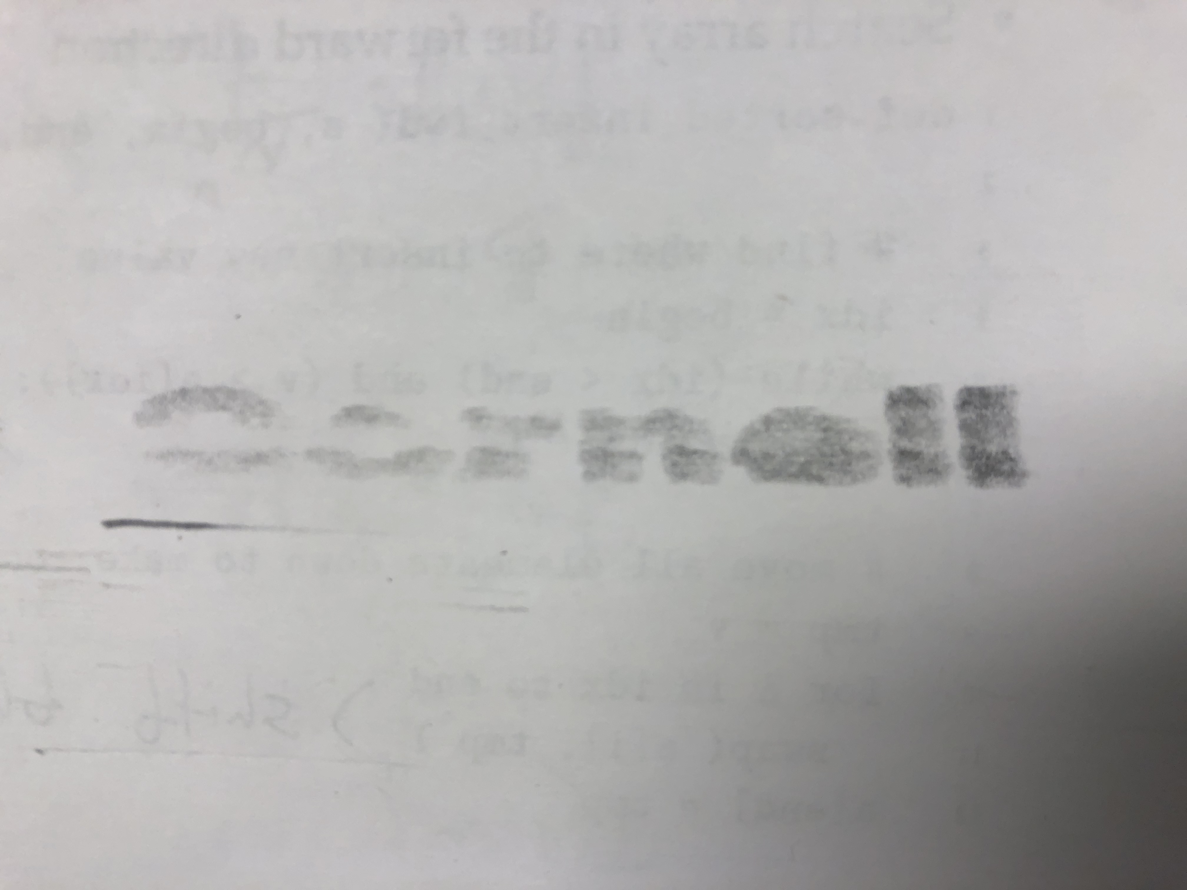
The first picture is the orginal picture while the second picture is the drawing.
So the group switch the x axis and y axis to solve this problem, in this way the effects of the belt stucks will be decrease to the minimum and will perform as expected. After the switch, the group run the program again to draw the same picture and get a more precise result.
 Figure 9. Fixed Test
Results
Regardless of certain deviation due to the hardware limitation, the design and implementation of the RPI printer meets the objectives and is able to print most of the input image in black and white. However, the steps the group took to meet the requirement is hard, which cost time and effort, especially the part to build the chasis. In addition, the system is mostly build on a handcrafted structure so there will be great potential for the future. The deviation inside the device is also caused by the uncareful design, so if the group can use 3-D printing instead, the group are suppose to have a better performance. The following images are outputs of the printer.
Video 1. Cornell Logo Printing
Video 2. Mickey Logo Printing
Conclusion
At last, the RPI printer will be able to print most of the picture which has a size in 400*400. It will be able to convert the colorful image to gray scale and print the black and white picture base on the threshold. Because of the limitation of the device, it will definitely not work to print a precise pixel points that cannot be determined by the pencil.
Future Work
If the group can have more time and budget to do this project, the precision problem can be fixed by using a 3-D printing model instead of a handcraft wood structure. In addition, use a more precise drawing tool and more reliable drive system, the group will be able to print the input picture into a gray scale output. At last, by adding a camera, the group will be able to realize the function to instantly transfer to picture that just taken to a draw.
Budget
Woods------------------$10
Metal Rods * 4 --------$10
Step Motor * 5 --------$13
Screws( Several ) -----$6
In total --------------$39
Team Contributions
Kaichen Wei: Taking charge of the hardware cutting, RPI circuit designing and Python programming.
Neo Yuan: Taking charge of the hardware structure designing, wood assemblying, and general testing for the printer.
Acknowledgments
Prof. Skovira - Advise on hardware, software, everywhere, provider of everything
Canhui Yu - Advise on the hardware construction and testing